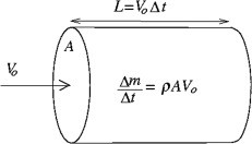
To understand the power contained in the wind one can consider an area normal to the wind velocity as shown in Fig. 9.1. After a time Δt the volume of air particles that has passed this area is A⋅Vo⋅Δt, (where A is the cross-sectional area and Vo is the velocity) weighing Δm=ρ⋅A⋅Vo⋅Δt (where ρ is the density) and having a kinetic energy Ekin=1/2ΔmVo2=1/2ρVo3AΔt and thus the available power (energy per time) in the wind is Pavail=1/2ρVo3A. The available power is thus proportional to the density of the air, the rotor area, and very importantly the wind speed cubed, and it is the purpose of any wind turbine to transform as cheap as possible some of this into useful power.
A wind turbine is a device that converts kinetic energy from the wind into mechanical energy. If the mechanical energy is used to produce electricity, the device may be called a wind generator or wind charger. If the mechanical energy is used to drive machinery, such as for grinding grain or pumping water, the device is called a windmill or wind pump. Developed for over a millennium, today’s wind turbines are manufactured in a range of vertical and horizontal axis types. Modern wind turbine sizes range from 50 kW to more than 5 MW. The smallest turbines are used for applications such as battery charging or auxiliary power on sailing boats; while large grid-connected arrays of turbines are becoming an increasingly large source of commercial electric power.
Wind turbines in locations with constantly high wind speeds bring best return on investment. With a wind resource assessment it is possible to estimate the amount of energy the wind turbine will produce.
A quantitative measure of the wind energy available at any location is called the wind power density (WPD). It is a calculation of the mean annual power available per square metre of swept area of a turbine, and is tabulated for different heights above ground. Calculation of wind power density includes the effect of wind velocity and air density. Colour-coded maps are prepared for a particular area described, for example, as ‘mean annual power density at 50 m’.
Types of wind turbines
Wind turbines can rotate about either a horizontal or a vertical axis, the former being both older and more common.
Horizontal axis
Horizontal-axis wind turbines (HAWT) have the main rotor shaft and electrical generator at the top of a tower, and must be pointed into the wind. Small turbines are pointed by a simple wind vane, while large turbines generally use a wind sensor coupled with a servo motor. Most have a gearbox, which turns the slow rotation of the blades into a quicker rotation that is more suitable to drive an electrical generator.
Since a tower produces turbulence behind it, the turbine is usually positioned upwind of its supporting tower. Turbine blades are made stiff to prevent the blades from being pushed into the tower by high winds. Additionally, the blades are placed a considerable distance in front of the tower and are sometimes tilted forward into the wind a small amount.
Downwind machines have been built, despite the problem of turbulence (mast wake), because they don’t need an additional mechanism for keeping them in line with the wind, and because in high winds the blades can be allowed to bend which reduces their swept area and thus their wind resistance. Since cyclical (that is repetitive) turbulence may lead to fatigue failures, most HAWTs are of upwind design.
Subtypes
(a)
12th-century windmills: These squat structures, typically (at least) four bladed, usually with wooden shutters or fabric sails, were developed in Europe. These windmills were pointed into the wind manually or via a tail-fan and were typically used to grind grain. In the Netherlands they were also used to pump water from low-lying land, and were instrumental in keeping its polders dry.
(b)
19th-century windmills: The Eclipse windmill factory was set up around 1866 in Beloit, Wisconsin and soon became successful building mills for pumping water on farms and for filling railroad tanks. Other firms like Star, Dempster, and Aeromotor also entered the market. Hundreds of thousands of these mills were produced before rural electrification and small numbers continue to be made. They typically had many blades, operated at tip speed ratios not better than one, and had good starting torque. Some had small direct-current generators used to charge storage batteries, to provide power to lights or to operate a radio receiver.
(c)
Modernwind turbines: Turbines used in wind farms for commercial production of electric power are usually three-bladed and pointed into the wind by computer-controlled motors. These have high tip speeds of up to six times the wind speed, high efficiency, and low torque ripple, which contribute to good reliability. The blades are usually coloured light gray to blend in with the clouds and range in length from 20 to 40 m (65 to 130 ft) or more. The tubular steel towers range from 200 to 300 ft (60 to 90 m) tall. The blades rotate at 10–22 revolutions per minute. A gear box is commonly used to step up the speed of the generator, although designs may also use direct drive of an annular generator. Some models operate at constant speed, but more energy can be collected by variable-speed turbines which use a solid-state power converter to interface to the transmission system. All turbines are equipped with shutdown features to avoid damage at high wind speeds.
Advantages of HAWT
- Variable blade pitch, which gives the turbine blades the optimum angle of attack. Allowing the angle of attack to be remotely adjusted gives greater control, so the turbine collects the maximum amount of wind energy for the time of day and season.
2. The tall tower base allows access to stronger wind in sites with wind shear. In some wind shear sites, every 10 m up, the wind speed can increase by 20 per cent and the power output by 34 per cent for every 10 m in elevation.
3. High efficiency, since the blades always move perpendicularly to the wind, receiving
power through the whole rotation. In contrast, all vertical axis wind turbines, and most proposed airborne wind turbine designs, involve various types of reciprocating actions, requiring airfoil surfaces to backtrack against the wind for part of the cycle. Backtracking against the wind leads to inherently lower efficiency.
4. The face of a horizontal axis blade is struck by the wind at a consistent angle regardless of the position in its rotation. This results in a consistent lateral wind loading over the course of a rotation, reducing vibration and audible noise coupled to the tower or mount.
Disadvantages of HAWT
1. HAWTs have difficulty operating in near ground, turbulent winds.
2. The tall towers and blades up to 90 m long are difficult to transport. Transportation can now cost 20 per cent of equipment costs.
3.Tall HAWTs are difficult to install, needing very tall and expensive cranes and skilled operators.
4.Massive tower construction is required to support the heavy blades, gearbox, and generator.
5.Reflection on tall HAWTs may affect side lobs of radar installations creating signal clutter, although filtering can suppress it.
6.Their height makes them obtrusively visible across large areas, disrupting the appearance of the landscape and sometimes creating local opposition.
7.Downwind variants suffer from fatigue and structural failure caused by turbulence when a blade passes through the tower’s wind shadow (for this reason, the majority of HAWTs use an upwind design, with the rotor facing the wind in front of the tower).
8.HAWTs require an additional yaw control mechanism to turn the blades toward the wind.
9.In order to minimise fatigue loads due to wake turbulence, wind turbines are usually sited a distance of 5 rotor diameters away from each other, but the spacing depends on the manufacturer and the turbine model.
Vertical Axis Wind Turbines
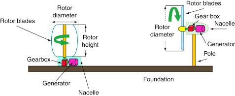
Vertical axis wind turbines (or VAWTs) have the main rotor shaft arranged vertically. Key advantages of this arrangement are that the turbine does not need to be pointed into the wind to be effective. This is an advantage on sites where the wind direction is highly variable. VAWTs can utilise winds from varying directions. With a vertical axis, the generator and gearbox can be placed near the ground, so the tower doesn’t need to support it, and it is more accessible for maintenance. Drawbacks are that some designs produce pulsating torque. Drag may be created when the blade rotates into the wind.
It is difficult to mount vertical-axis turbines on towers, meaning they are often installed nearer to the base on which they rest, such as the ground or a building rooftop. The wind speed is slower at a lower altitude, so less wind energy is available for a given size turbine. Air flow near the ground and other objects can create turbulent flow, which can introduce issues of vibration, including noise and bearing wear which may increase the maintenance or shorten the service life.
However, when a turbine is mounted on a rooftop, the building generally redirects wind over the roof and this can double the wind speed at the turbine. If the height of the rooftop mounted turbine tower is approximately 50 per cent of the building height, this is near the optimum for maximum wind energy and minimum wind turbulence.
Subtypes
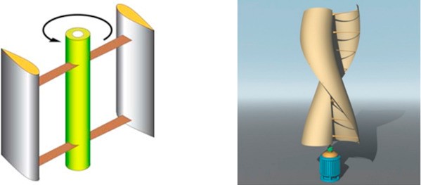
Darrieuswind turbine: ‘Eggbeater’ turbines or Darrieus turbines, were named after the French inventor, Georges Darrieus. They have good efficiency, but produce large torque ripple and cyclical stress on the tower, which contributes to poor reliability. They also generally require some external power source or an additional Savonius rotor to start turning, because the starting torque is very low. The torque ripple is reduced by using three or more blades which results in greater solidity of the rotor. Solidity is measured by blade area divided by the rotor area. Newer Darrieus type turbines are not held up by guy-wires but have an external superstructure connected to the top bearing.
Giromill: A subtype of Darrieus turbine with straight, as opposed to curved, blades. The cycloturbine variety has variable pitch to reduce the torque pulsation and is self-starting. The advantages of variable pitch are: high starting torque; a wide, relatively flat torque curve; a lower blade speed ratio; a higher coefficient of performance; more efficient operation in turbulent winds; and a lower blade speed ratio which lowers blade bending stresses. Straight, V or curved blades may be used.
Savonius wind turbine: These are drag-type devices with two (or more) scoops that are used in anemometers, Flettner vents (commonly seen on bus and van roofs), and in some high-reliability low-efficiency power turbines. They are always self-starting if there are at least three scoops. They sometimes have long helical scoops to give a smooth torque.
Advantages of vertical axis wind turbines
1.A massive tower structure is less frequently used, as VAWTs are more frequently mounted with the lower bearing mounted near the ground.
2.Designs without yaw mechanisms are possible with fixed pitch rotor designs.
3.The generator of a VAWT can be located nearer the ground, making it easier to maintain the moving parts.
4.VAWTs have lower wind start-up speeds than HAWTs. Typically, they start creating electricity at 6 mph (10 km/hr).
5.VAWTs may be built at locations where taller structures are prohibited.
6.VAWTs situated close to the ground can take advantage of locations where mesas, hilltops, ridgelines, and passes funnel the wind and increase wind velocity.
7.VAWTs may have a lower noise signature.
Disadvantages of vertical axis wind turbines
1.A VAWT that uses guy-wires to hold it in place puts stress on the bottom bearing as all the weight of the rotor is on the bearing. Guy wires attached to the top bearing increase downward thrust in wind gusts. Solving this problem requires a superstructure to hold a top bearing in place to eliminate the downward thrusts of gust events in guy wired models.
2.The stress in each blade due to wind loading changes sign twice during each revolution as the apparent wind direction moves through 360 degrees. This reversal of the stress increases the likelihood of blade failure by fatigue.
3.While VAWTs’ components are located on the ground, they are also located under the weight of the structure above it, which can make changing out parts very difficult without dismantling the structure, if not designed properly.
4.Having rotors located close to the ground where wind speeds are lower due to the ground’s surface drag, VAWTs may not produce as much energy at a given site as a HAWT with the same footprint or height.
Turbine design and construction
Wind turbines are designed to exploit the wind energy that exists at a location. Aerodynamic modelling is used to determine the optimum tower height, control systems, number of blades and blade shape. Wind turbines convert wind energy to electricity for distribution. Conventional horizontal axis turbines can be divided into three components.
1.The rotor component, which is approximately 20 per cent of the wind turbine cost, includes the blades for converting wind energy to low speed rotational energy.
2.The generator component, which is approximately 34 per cent of the wind turbine cost, includes the electrical generator, the control electronics, and most likely a gearbox (e.g. planetary gearbox, adjustable-speed drive or continuously variable transmission) component for converting the low speed incoming rotation to high speed rotation suitable for generating electricity.
3.The structural support component, which is approximately 15 per cent of the wind turbine cost, includes the tower and rotor yaw mechanism.
Small wind turbines
Small wind turbines may be as small as a fifty-watt generator for boat or caravan use. The US Department of Energy’s National Renewable Energy Laboratory (NREL) defines small wind turbines as those smaller than or equal to 100 kW. Small units often have direct drive generators, direct current output, aeroelastic blades, lifetime bearings, and use a vane to point into the wind.
Larger, more costly turbines generally have geared power trains, alternating current output, flaps and are actively pointed into the wind. Direct drive generators and aeroelastic blades for large wind turbines are being researched.
Rotor
To increase the efficiency of wind turbines, rotor planning principles are very important for wind turbines with horizontal axis. It is not possible to expect the maximum efficiency from a wind turbine that is installed without doing the optimisation processes. At this point,rotor blades aerodynamic features are very important. It is necessary to put forward the power value that can be obtained from rotor blades. It is possible to conduct power tests indoors or under natural conditions. But in both methods, real rotor blades have to be produced. And this means cost. For this reason, first miniature blades can be produced and the tests can be conducted on these miniature rotor blades.
The main forces in atmosphere that produce wind and effect its speed is: pressure grading force, diverting force, centrifugal force andfriction force.Pressure gradient force acts to move the air from high pressure to low pressure. Diverting force affects the air from two ways: one is as diverting force of earth’s rotation for movements from the equator to poles or in the opposite direction. Winds, in general, are under the effect of a force that wants to divert them from their centre because they curl around a centre. This force is called centrifugal force. Friction force tries to decrease the speed of wind. The effect of this forces the greatest when near to earth’s surface.
Importance of Rotor
Rotor is the organ that transforms the kinetic energy of wind to mechanic energy. For this reason it is very important for wind turbines. It is very important for rotor and rotor blades to have optimum features, because these have a direct effect on the efficiency of wind turbines.
A flow mass has a kinetic energy because of its speed.
E=M2V2
The achievement derives from the energy per time. Calculation of the mass flow:
m=ρ·V·A
Into these conditions we can compute the power with the following equation:
P=ρ2.A.V3
Power equity gives the theoretic power that can be obtained from the kinetic energy that is stored in wind as Watt. This theoretic power has to be transformed into useful power by the help of turbine rotor. At this point a constant, which is effected by wind speed, turbine shaft speed and blade choice has to be taken into consideration. This constant is called ideal power constant (Cp). Blade types, blade form, inclination angle and speed of blade’s tip are effective factors in here. In Fig. 2 the diagram of the ideals power coefficient. Theoretically ideal power constant cannot exceed 0.59. This constant is called Betz constant. In practice, this value is even smaller, because mechanical losses (η) come into effect in practice. But mechanic efficiency value can be neglected in calculations, because it is close to 1. Thus the equation can be written as below:
P=ρ2.A.V3.Cp.η
One thing that must not be forgotten in here is that air density is 1.225 kg m−3 under standard meteorological conditions (temperature: 15°C and air pressure: 1013.3 hPa). The changes in air temperature and air pressure will change air density.
Obtaining maximum energy production from a wind turbine depends on various factors. These are factor like the height of wind turbine; wind turbine blade’s sweep area and aerodynamic structure, air density and wind speed. The most important ones of these factors are the height of wind turbine and aerodynamic structure of wind turbine. The height of wind turbine is important because wind speed increases as we go away from earth’s surface. Aerodynamic structure of wind turbine blade is important, because it can transform maximum 59% of the kinetic energy that wind has to useful energy.
Rotor aerodynamic of wind turbine: In transformation of wind energy, which is formed by heating of different points of the atmosphere by the main energy source sun, to electric energy; wind rotor, which is the first ring in transformation chain, can be designed according to Betz or Glaubert–Schmitz for the purpose of transferring the existing wind power with minimum loss.
Wind turbine rotor height: As wind speed gets away from earth’s surface, it frees itself from the friction effect cause by the roughness of earth’s surface. Thus it moves more freely. As it gets away from obstacles that decelerate its speed, its speed increases. It is assumed that winds that are 1000 m above the earth’s surface, namely geostrophic winds are not affected by the roughness of earth’s surface and friction losses. At the light of these thoughts, we can say that there is a relation between wind speed and wind height. This is the reason why wind turbines are built as high as possible.
Wind turbine rotor diameter: Besides determining turbine height, the diameter of the wind that rotor blade sweeps has to be determined. The diameter of the wind that rotor blade sweeps has a direct effect on the power that will obtain from turbine.
The wind potential in where the wind turbine rotor will operate: Wind potential in where the wind turbine will installed is very important. For this reason it is one of the parameters that have to be considered in rotor design. Wind speed potential in where the wind turbine will installed has to be observed at least for 6 months. Wind potentials is directly effective on the efficiency of the wind turbine rotor. Wind speed is the most important factor about the energy of the wind. The power that will be obtained from wind is directly proportional to wind speed’s third power.
When wind speed has this much effect on the power that will be obtained from the wind turbine, the wind potential in where the turbine will be built is very important. The main objective is to find the point where the wind speed is maximum and install the turbine there.
Land structure of the place where the wind turbine rotor will operate: There is a relation between wind speed and wind height. This relation is dependent on some conditions. These conditions originate from land shapes. Same conditions do not apply in a flat land surface and surface with obstacles. In a flat land surface as height increases, speed also increase in a direct ratio, but his will not be true in a land surface with obstacles. In a surface with obstacles, wind will have to climb over obstacles to resume its course and this will cause a pause in wind’s speed.
If the most important criteria for obtaining energy from wind are wind speed, then it is very important to find the areas where wind speed is high and install wind turbine rotor there. But we don’t have to make a false assumption that when we increase the height we will always catch winds that contain more energy. The factors that wind speed is affect depending on height are: Von Karman constant, surface friction speed and roughness length.
The performance demanded from wind turbine rotor: Before choosing a wind turbine for an enterprise, first we have to determine how much electric power our enterprise needs. This way, power of the wind turbine that will be installed can be determined. The performance demanded from the rotor has to be determined according to the enterprise’s installed power.
To increase the efficiency of wind turbines, rotor planning principles are very important for wind turbines with horizontal axis. It is not possible to expect the maximum efficiency from a wind turbine that is installed without doing the optimisation processes.
Like in every topic, to be successful when making use of wind energy, basic values must be based on scientific data. When the topic is considered from this point of view, rotor design parameters have to be put forward in wind turbines. Starting from here, the most suitable systems can be developed by taking source data as a basis. The basic strategy is to put into practice high performance systems that can compete.
Wind Turbine
A wind turbine is a device that converts kinetic energy from the wind into mechanical energy which is further converted into electrical power in a wind power plant.
Wind turbine structure
Awind turbine is a rotating machine which converts kinetic energy extracted from wind into mechanical energy by rotating blades. Then, this mechanical energy is converted into electricity through a generator. Fig. 3 shows the basic components of a wind turbine. In the following paragraphs, a brief overview of wind turbine and its basic components is presented.
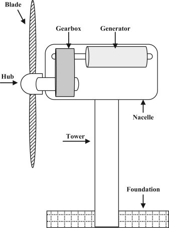
Wind turbines consist of six major components including rotor, nacelle, tower, gearbox, generator, and foundation of the system. The rotor is connected to the blades through a hub and extracts kinetic energy from the wind and converts it into mechanical energy.
The enclosure at the top of the tower is nacelle which is the main structure and contains major components like turbine generator, gearbox, drive train, electronic control system, and interface to connect with the power grid.
The drive train is composed of different mechanical components and systems which consist of bearings and shaft. Application of drive train in the wind turbine is in interconnecting the hub, gearbox, and generator.
The gearbox׳s function is to increase rotational speed of the low speed shaft. Therefore, the purpose of a gearbox is to transform the low speed revolution into high speed revolution. It is connected to an electric generator through high speed shaft. The generator transforms the rotational mechanical energy into electrical energy, the output of which is then connected to the electrical grid station for supplying electrical energy.
The whole structure of wind turbine is supported by a tower fastened to system foundation and raises nacelle to the height at which maximum wind speeds can be extracted.
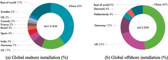
The wind turbine is a leading technology for extracting energy from wind. It has been extensively studied with the dwindling fossil fuel reserves and the growing awareness on building environmental friendly energy supplies. The sustainability metric assessment on the lowest relative emissions of greenhouse gases, lower use of water, and the most favourable social impacts showed the dominance of wind power on hydropower, photovoltaic and geothermal energy. With an addition of 77.6 GW in the year 2022, the projected global wind power capacity is 906 GW, as shown in Fig. 1. The Indian government recently set a target of 450 GW of overall renewable energy by 2030, with wind energy and solar photovoltaic estimated to account for 36 % of total installed capacity.
The future of wind power is mainly dependent on the development of vertical axis wind turbines (VAWTs) because of their applicability in low wind regions, especially urban areas. The VAWTs can be classified into two main categories, i.e., drag and lift-based. The Savonius rotor is driven by the aerodynamic drag force acting in the direction of the wind, whereas lift-based turbines (Darrieus and H-type) experience the force acting in the perpendicular direction of wind flow. Savonius rotors work at lower wind speeds than Darrieus rotors, resulting in better self-start capabilities. In contrast, the performance of Savonius rotors in terms of power coefficient is lower than that of the other VAWTs due to the limitation of a lower tip speed ratio. VAWTs possess omnidirectional behaviour, higher scalability, and better performance in chaotic, unstable, and turbulent flow conditions. VAWTs also exhibit a higher degree of sustainability than horizontal axis wind turbines (HAWTs) because of its simplified design layout and low maintenance with no yaw or pitch mechanics, lower noise pollution, better safety, lower operational tip ratio, lower centre of mass, and the generator not being limited to the top of the tower. Over the last decade, on-site implications of the VAWTs have been observed to gain more attention with the increase in its self-starting abilities. The VAWT is also proven to be a more feasible technology because of its lower installation, operation, and maintenance costs. In general, VAWTs (>10 MW), which are larger in size, provide a lower cost of energy (COE) when compared to HAWTs.
There are also certain challenges associated with VAWTs, such as the formation of a wake on the VAWTs blade, which is one of the most common undesired phenomenon. Wakes increase the turbulence intensity in the flow, and this turbulent wake flow produces dynamic stall characteristics and influences the aerodynamic loads during the downstream operation of wind turbines. Further, the turbine reaction force results in a decrease in wind speed and a change in wind direction, which increases downstream fatigue and substantially lowers the wind farm’s economic efficiency.
The biggest challenge which affects the VAWTs performance and stability is dynamic stall. The dynamic stall phenomena is most noticeable in the Darrieus rotor at low tip speed ratios (TSRs). It occurs whenever the airfoil angle of attack (AoA) exceeds the static stall angle during unsteady flow conditions. The Vortices development and shedding cause fatigue stress, excessive noise levels, and unwanted vibrations over the blade. This unstable phenomenon also produces fluctuating torque, which is one of the major cause of low turbine power. Moreover, the dynamic stall behaviour is generally dependent on the Re, flow amplitude, Mach number, airfoil shape, and reduced frequency. On the other side, for a high AoA, the most predictable type of dynamic stall is the production of a wide-scale dynamic stall vortex (DSV) from the blade’s leading edge (LE). Ultimately, it appears that this phenomenon increases the lift coefficient (CL) for a shorter period than the maximum CL at static stall and then suddenly decreases lift, overall performance, and system stability.
The phenomena of dynamic stall have been widely studied using experimental and numerical techniques over the years. Experimentation has relied on techniques such as particle image velocimetry (PIV) and laser doppler velocimetry (LDV) to identify the flow characteristics over an airfoil or an entire wind turbine. Computational fluid dynamics (CFD) has significantly contributed to boost experimental investigations. The full-scale VAWTs (>10 kW) testing in the wind tunnel is quite complicated due to unwanted high tunnel-blocking effects. Typically, the experimental data from models have been utilised to validate numerically calculated values. The numerical studies on full-scale turbines are generally performed to optimize the parameters, but the lack of sufficient experimental measurements shows inherent validation challenges. The variations in the local wind velocity limit the experimental study on VAWTs due to the involvement of systematic and random uncertainties. In most situations, the Cp of the turbine is generally determined as an integral performance measure that is restricted in validation and can exclude crucial data variations for the investigation of the dynamic stall. In addition, critical knowledge such as generator performance, strut geometry, and blade-strut attachment architecture is often unavailable. It is observed that an individual VAWT airfoil test in a wind tunnel would provide the most accurate depiction of a dynamic stall.
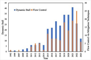
The studies on stalled formation were typically carried out to prevent the separation of the boundary layer (BL). The fluid stream in BL passes across the airfoil’s upper (suction) surface and accelerates toward the LE. The stream slows down as it approaches the TE due to adverse pressure gradients condition. If the stream’s kinetic energy is lower to overcome the pressure gradient, it tends to separate from the surface and form separation vortices, ultimately it leads to the formation of DSV. The mechanism for suppressing the DSV can be achieved by controlling the flow and implementing various mitigation techniques. This can be done in two ways, i.e., (i) re-energize the boundary layer (BL) by mixing, (ii) controlling the flow separation and backflow over time or building up the counter flow at positions other than LE. Further, the mitigation of dynamic stall can be achieved through two strategies: passive flow control which doesn’t require external energy input and active flow control requires external energization. Mitigation of the dynamic stall continues to be a research priority for the scientific community, as it will substantially improve the performance of VAWT. Data on the prevalence of Dynamic stall and methods for preventing it has been compiled from a wide range of sources, including journal papers, reviews, and conference articles. Fig. 2 depicts 22 years of research output in a documented form on the dynamic stall and its mitigation techniques for VAWTs. One can understand from the figure that till 2014 the amount of research conducted on wind turbine’s stalling and mitigation phenomena was less and afterwards, there was a sudden jump of almost 3.5 times in research on dynamic stalls as well as mitigation. The plausible reasons are the availability of advanced computational facilities, upgraded CFD packages, and sophisticated measuring devices for experimental work. The necessity of dynamic stall mitigation has been the subject of increased study during the past four years, demonstrating the importance of flow control strategies in VAWTs.
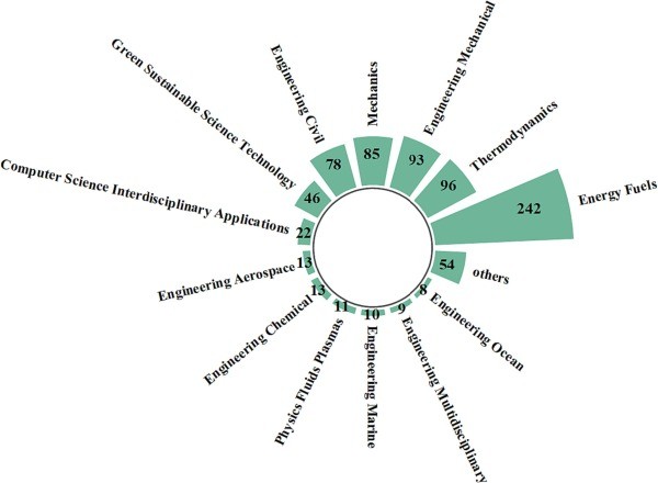
Scientometric assessment is referred as a quantitative analysing technique used for data driven insights into different aspects of scientific research area, as shown in Fig. 6. The top four disciplines that contribute the most to the overall document count are Energy Fuels, Thermodynamics,Engineering Mechanical, and Mechanics. These four disciplines are responsible for approximately 31 %, 12 %, 12 %, and 11 % of the subject topic’s papers, which accounts for a total contribution of 66 % to the document count.
In VAWTs, the more focus is on the performance analysis and flow control techniques considering the single blade analogy and particular operating range. However, only a few studies independently define the formation and mitigation of vortex, separation regions, and dynamic stalls. Hence, a detailed literature is much needed to discuss the formation and mitigation of the stall considering the combination of active and passive approaches to improve the VAWTs performance. The vortex shed must be thoroughly defined, and the performance parameters must be optimized to prevent the formation of a dynamic stall. In this process, the important findings from various literature are discussed and summarised sequentially in the present article to select some appropriate techniques for maximizing the VAWTs performance. This paper is divided into three main important sections. Firstly, the impact of dynamic stall on VAWTs performance is presented followed by the mechanism of formation of dynamic stall and lastly, the important theories are highlighted. Finally, themitigation strategies for controlling dynamic stall are presented. The paper summarises quantitative and qualitative assessment of the technical findings on formation and mitigation of stall. In addition, authors have identified some key areas where more lights need to be thrown in futureresearch work.
Modern Wind Turbine
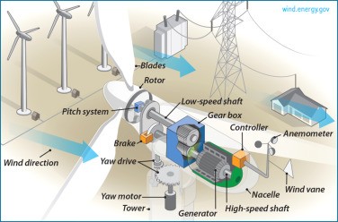
Wind turbine is a generic name for the windenergy system as a whole that converts the KE in wind into electrical energy. Modern wind turbine sizes range from 50 kW to more than 5 MW. Wind turbines are available in a variety of designs and power ratings, but the most familiar design is the horizontal axis propeller type wind turbine which is shown in Fig. 5.3 in a simplified form. The basic components of the wind turbine are:
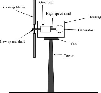
1.Tower: A tower carries the rotating blades at a satisfactory height to increase the exposure of the blades to wind. Large wind turbines (in the MW range) have towers as high as 250 m above the base.
2.Rotating blades: Rotating blades intercept the KE of wind. Blades are generally made of fiberglass-reinforced polyester or wood-epoxy material. The length of the rotating blades ranges from 5 m to over 60 m. The majority of wind turbines have three rotor blades. The pitch angle of the blades is changeable by advanced blade systems in modern wind turbines in order to maximize the capture of the wind’s KE.
3.Yaw mechanism: A yaw (the left–right motion) mechanism allows the housing box to turn and maintains the blades perpendicular to the wind speed, thereby increasing the exposure of the blades to the wind.
4.Gearbox: A gearbox is used to connect the low-speed rotating blades to the high-speed generator. It also serves as a clutch.
5.Generator: A generator is connected to the high-speed shaft of the gearbox to transform the mechanical energy of the rotating blades into electrical energy.
6.Controller: A controller connects the utility system to the wind generator and locks the blades when the wind speed is less than the minimum generation limit or when the wind speed surpasses the design restrictions of the system.
Aeroelasticity and structural dynamics of wind turbines
The wind turbine is a flexible structure that operates mainly under the action of the aerodynamic loads on the rotor. The airflow passing through the rotor, besides rotating the blades, also deforms the whole structure. As the wind turbine deforms, the elastic motion of the various components affects the aerodynamic loading, which in turn differentiates the deformation field. In this way, the coupled aerodynamic–structural dynamic problem is formed.
Aeroelastic analysis of a wind turbine lies in determining the elastic deflections and internal loads along the various components, arising from its interaction with the incoming wind. It is understood that this is a very important task in the design process since it provides the design limits for the dimensioning of the individual components. However, given the stochastic nature of the wind, the unsteadiness of the flow over the rotor blades, the complex structure of the blades and the different degrees of freedom (DOFs) of motion undergone by the various components (rotor rotation, blades pitching, nacelle yaw, etc.), it is also understood that it is by no means an easy task.
The present chapter consists of two parts. In the first part, the modeling of the wind turbine structural dynamics and aeroelastics is described in the context of the beam theory and finite element analysis, as applied in most current design and analysis tools. In the second part, the main aspects toward improved aeroelastic design are discussed. This part begins with describing the nature of the external loads on a wind turbine. Then, aeroelastic instability problems encountered in the past or expected in the future designs, methods for improving aeroelastic behaviour of wind turbines and some future trends concerning aeroelastic design are discussed.
Energy Management
Wind turbine
A device (mechanism) that converts the kinetic energy of wind into the electrical energy. Thus, a wind turbine can be considered as a transducer and is a modified form of its primitive ancestor the windmill. Like a simple loop AC machine, in a wind power system, wind causes the turbine’s blade to rotate, which causes the generator to turn to generate electricity at its output. As per fundamental principles of electric power generation, the induced electromotive force (emf), (potential) is proportional to the mechanical speed of the generating device:
eind=kϕω
where k is the machine construction constant, ϕ is the flux in the machine, and ω is the rotational speed (rad/s).
The wind turbine rotates at a low speed due to the noise and mechanical strength factors and at such a low speed there will be no considerable transduction of mechanical rotation to an electric voltage. Thus, a low speed shaft (connected to the blades) translates the low rpm of blades to high rpm using a high speed gear for the electric generator. The speed ratios can be typically as high as 1:100. The electrical output is than fed to the power system lines (grid).
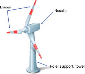
Modern wind turbines are designed in standard and peculiar designs. A simple wind turbine design consists three basic parts, a pole (called tower), set of blades, and a system box called a nacelle. The pole stands with the complete assembly to provide the height to the blades for air access, blades are used to produce rotation in generating assembly (or the rotor to the generator) and nacelle is used as a housing that contains the internal generating machine and assembly, including the generator, gearbox, drivetrain, and brake assembly, etc. (Figs. 73 and 74).
Wind Turbine Types
Wind turbines are manufactured in diverse designs, and are broadly distributed in two major categories with respect to their axis:
1.Horizontal axis – HAWT
2.Vertical axis – VAWT
The blades must be facing the air push, it is their orientation that describes the axis of the turbine.
Aerodynamic efficiency of the system, cost, and system reliability are main factors those help to decide the number of blades in a certain turbine.
The horizontal axis turbines are more popular, where one to many blades, (most commonly two to three) are mounted to the pole support by a shaft. The shaft rotor and nacelle (electrical generator) are mounted at the top of a tower, where the blades must be in the wind direction. A simple wind vane points the turbines in the wind, while a servo motor-based sensor mechanism can aid larger turbines to get the required direction. A gearbox translates the rotation of the blades as per the requirements of electrical generation mechanism. The horizontal turbines are further categorized as upwind and downwind facing. Figure below shows an example of horizontal turbine field installed at the Jhampir power plant (near Karachi Pakistan), the first wind power plant of Pakistan, completed in 2002 and its total capacity is 50 MW. This wind region has a potential of 50,000 MW whereas the average wind speeds there is more than 7 m/s. (Fig. 10).
The second type, the vertical axis design, uses upright assembly of the blades and rotor shaft, perpendicular to the ground surface. This clever assembly unlike the horizontal design, gets the air push regardless of the wind direction. Savonius, and Darrieus blades wind turbines are examples of vertical designs (Fig. 11).
In both designs the rotor is mounted with a tower, as described earlier to get stronger blow of the wind (vertically) away from the ground to get larger amount of electrical energy at better efficiency.
Typical values of larger assemblies are of 100 by 100 m (tower and blades).
Onshore Wind Energy
Wind turbines are based on the principle of converting the kinetic energy of awind resource into mechanical work, such as water pumping, or via mechanical work into electricity via a generator (Da Rosa, 2005). Nowadays, wind turbines produced worldwide are almost solely of the electricity-generating type, though mechanical turbines used for water pumping are still of essential use in some areas (Twidell and Weir, 2015). Wind turbines come in a variety of blade designs, but the most common types of wind turbine forelectricity generation, both on- and offshore, are horizontal axis turbines with three blades (IRENA, 2018).
Modern-day conventional (horizontal axis) wind turbines are built up from a steel or concrete tower, a yaw system between the tower and the nacelle (the housing for the hub section of the wind turbine) that orientates the wind turbine toward the wind, adrivetrain (gearbox or direct drive generator), aconvertor, and the rotor with the blades (Twidell and Weir, 2015). The inner structure of a wind turbine is shown in Fig. 11.
The power generated by a wind turbine is related to the quality of the wind, height of the tower (hub height), the rotor diameter, and management of operation and maintenance. In general, wind turbines are able to generate electricity at wind speeds between 3–5 and 25 m/s. The maximum electricity generation is usually achieved from 11 to 25 m/s (IRENA, 2018).
Wind Turbines (WT)
Nowadays, the use of wind energy for power generation is continually increasing. Fig. 3 shows the World wind power capacity from 1996 to 2012. The wind turbine is one of the commonly used renewable energy sources for the micro-grid systems. It converts the wind energy coming from air current flowing across the earth׳s surface into electrical energy. Depending on controllability, the operating systems of the wind turbine are classified into either variable speed wind turbines or constant speed wind turbines.
The turbine efficiency
the aerogenerator and the available energy at Betz limit, can be simply calculated by the following formula:
η=tA⁎PrPh,
where t the time period, A is the blade sweep area of wind turbine, Pr is the rated power of the wind turbine and Ph is defined as
Ph=t100012ρ¯vm3(h10)3α,
in which vm is the mean wind speed of this time period at the standard height
10 m, h is the hub height, α is the roughness factor similar as Eq. (1), and the
corrected air density ρ¯ (kg/m3) is determined by
ρ¯=P¯Rd⁎T¯,
where P¯ and T¯ are the mean air pressure and the mean air temperature in the time period t with the unit of N/m2 and Kelvin, respectively and Rd=287.
On the other hand, the turbine efficiency η, can be defined as the ratio between recoverable energy on the aerogenerator, ER (kWh/m2/year), and available energy at Betz limit, EA (kWh/m2/year). Last expression outlined in Refs. A simple estimating procedure can be introduced to estimate the monthly wind turbine efficiency by the following formula:
ηmonthly =720SaPrPh(mo.)
where Pr is the rated power of the used wind turbine (kW), Sa is the rotor swept area (m2).
Keeping all other points constant, adjusting the turbine isentropic efficiency results in some concerning results (Fig. below). A drop in turbine efficiency has a large effect on the turbine work available. A drop in efficiency from 90% down to 70% results in a drop in turbine work of 28.5%. Not only that, a drop in turbine efficiency has a direct effect on process heat available and net work, resulting in a reduction of the utilisation factor. During this analysis, pump work and input heat supplied remain constant.